Tutorial by: zshusveti
Prerequisites: Basic understanding of Controller, IAP and Airwave configuration.
RAPNG is the new architecture to provide corporate connectivity to the branch networks. Mostly it differs from normal RAP architecture that it uses IAPs on the remote side.
Benefits of using RAPNG:
- IAPs create a local cluster that provides ARM, wIDS/wIPS and other features - it means better and faster RF management.
-
It provides the survivability feature of Instant APs with the VPN connectivity of RAPs
- Since the RF management is local, the overhead is much smaller on the tunnel (1-2 Kbps for RAPNG vs. 50-60 Kbps for RAP)
- Only 1 PEFNG license is needed on the controller (just to enable some of the features). No need for AP/PEFNG/RFProtect licenses.
- Since the IAPs aren’t actually terminated on the controller the scalability is much better
Cons:
- Since 6.3 OS, 620 and 650 controllers doesn’t support IAP-VPN.
- Clients aren’t visible on the controller. Airwave is recommended for central monitoring.
- The controller can’t manage IAPs. Airwave is recommended for central management.
Controller: 3600 - OS 6.3.1.3
IAP: IAP-135 - 4.0.0.4
AirWave: 7.7.9
Required steps:
Part 1: Configuring the Controller
Part 2: Configuring IAP
Part 3: Configuring Airwave for monitoring and central management (optional)
Part 1: Configuring the Controller
Step 1:
First you need to add to the whitelist the mac address of the IAP. You may do this either via GUI or CLI. CLI command:
whitelist-db rap add mac-address 24:de:c6:xx:xx:xx ap-group rapng
(Note: The ap-group is not relevant, you can use any group name as it’s not used.)
Check if it’s in the db:
show whitelist-db rap

AP-entry Details
----------------
Name               AP-Group  AP-Name            Full-Name  Authen-Username  Revoke-Text  AP_Authenticated  Description  Date-Added                Enabled  Remote-IP
----               --------  -------            ---------  ---------------  -----------  ----------------  -----------  ----------                -------  ---------
24:de:c6:xx:xx:xx  rapng     24:de:c6:xx:xx:xx                                           Provisioned                    Tue Mar  4 11:46:28 2014  Yes      0.0.0.0

AP Entries: 1
Step 2:
The next step is to define a DHCP pool for the IAPs:
From CLI (you can use GUI as well):
ip local pool rapng 192.168.20.1 192.168.20.10
For a basic setup, this is all we need on the controller side.
Part 2: Configuring IAP
Step 1:
Login to IAP GUI.
From the top right menu choose More and VPN:

From the drop-down list select Aruba IPSec. Specify the primary host (along with the backup address if you have one). This is the IP address of the controller interface that will terminate the VPN connection.
(Note: You can use other protocols such as GRE, you need to check the Aruba Instant User Guide for details)
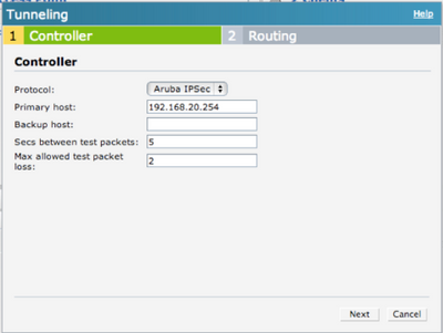
Click Next and you will see the Routing configuration page. You may specify which subnet should be routed to the tunnel. In this example all traffic is routed to the controller.
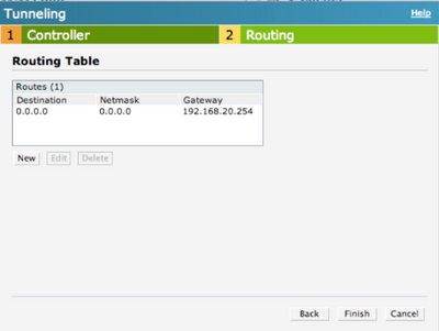
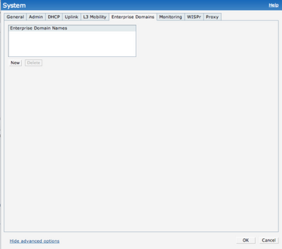
By default, IAP intercepts the DNS traffic and tries to source NAT it locally despite the routing table. If you need to tunnel the DNS traffic you need to specify the enterprise domains in the System settings:
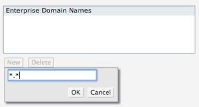
If you want to tunnel all DNS traffic you should use *.* wildcard.
If the UDP4500 traffic is allowed from the IAP to the host address you specified above, then you should see that the VPN connection is up.
You may also verify it on the controller by using the show iap table command or checking the Monitoring – Clients part of the GUI.
show iap table

IAP Branch Table
----------------
Name              VC MAC Address     Status  Inner IP      Assigned Subnet  Assigned Vlan
----              --------------     ------  --------      ---------------  -------------
Instant-XX:XX:XX  24:de:c6:xx:xx:xx  UP      192.168.20.1
Step 2:
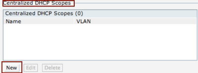
The next step is to define the VLANs that you want to use. In this example VLAN 100 is used. From the More menu choose DHCP Server.

There are several options for DHCP configuration on the IAP. In this example Centralized L2 DHCP configuration is used. This means that the VLAN physically exists only on the controller and the DHCP server is in the HQ (the IAP acts as a DHCP relay and forwards the DHCP requests to the controller over the VPN tunnel). For details of other options you may check the Aruba Instant User Guide.
Click on New.
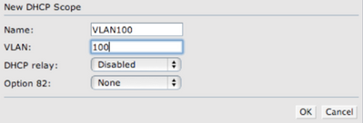
Enter the name for the VLAN and the VLAN ID. For basic setup the default DHCP relay and Option 82 parameters are fine.
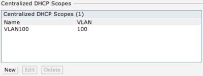
After clicking OK you should see VLAN name and it’s ID.
Step 3:
From this step you may use this VLAN for configuring network access (wired profiles, SSIDs, Dynamic VLAN assignment etc).
In this example a wireless network has been configured.
The SSID name is arubademo-corporate.
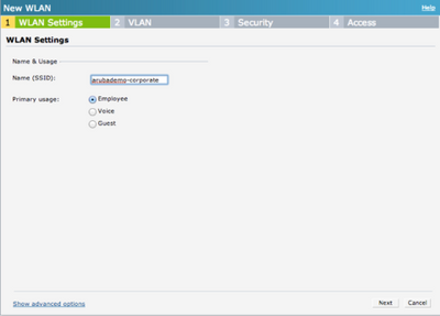
In the next step VLAN 100 is defined.
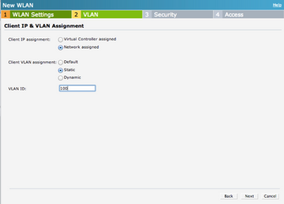
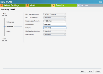
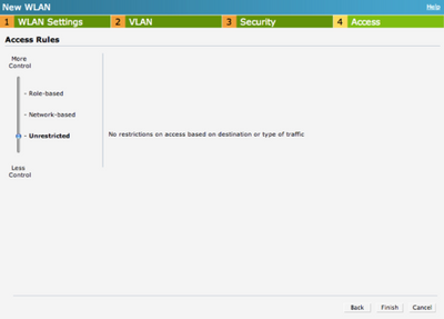
After this step you should be able to see the network and connect clients to it.
Part 3: Configuring Airwave for monitoring and central management (optional)
Step 1:
Go to System settings on the IAP GUI and look for the AirWave section on Admin tab.
You need to enter the following parameters:
- Organization: Based on this parameter AirWave will create a new Group for the IAP.
- Airwave server: The IP address of your AirWave server (you may specify the backup as well if you have one)
- Shared key: This can be anything, you will NOT need to enter this on the AirWave. This key is used for configuring the first AP in the Instant network.
(Note: You may use DHCP options to automatically configure the AirWave settings. Please check the Aruba Instant User Guide for details.)
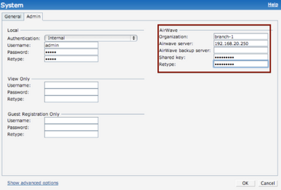
This is the only thing you need to configure on the IAP.
(Note: In this example all traffic is tunneled back to the HQ, the IAP communicates with AirWave from its VPN address - via HTTPS)
Step 2:
Assuming the communication is OK you should see your IAP as a new device on AirWave. Click on Add.
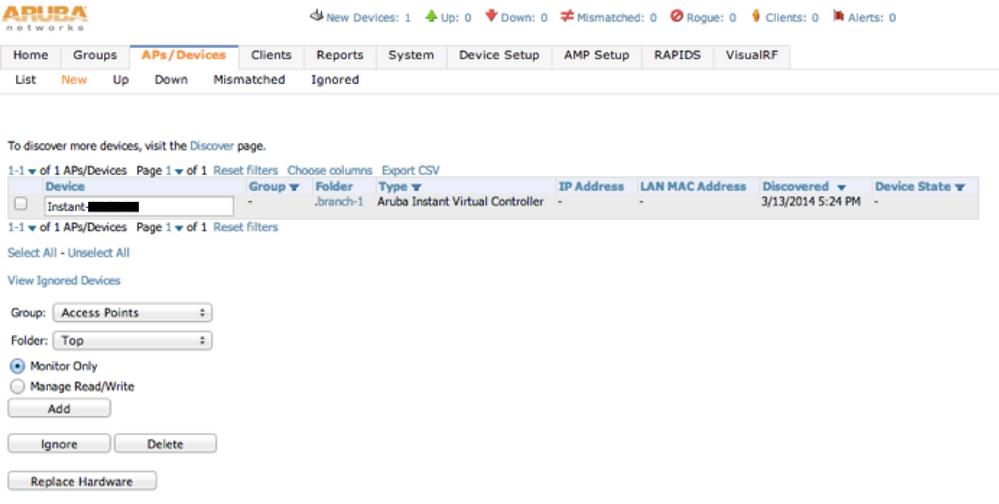
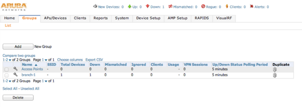
As you can see the group is automatically created. In this example “branch-1” was used.
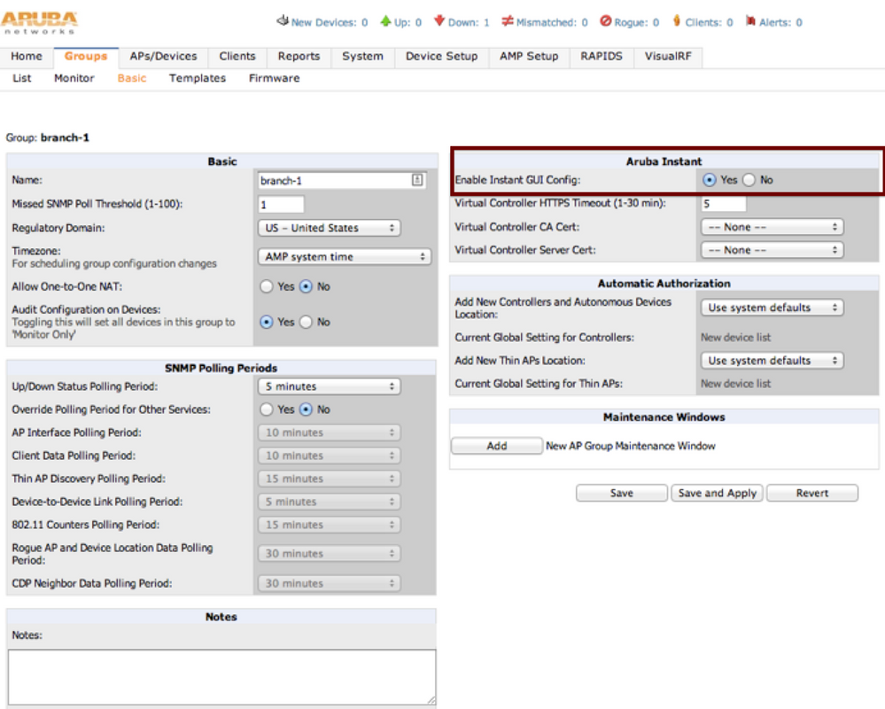
By default, AirWave provides template based management for the IAPs. If you want to use GUI config you need to click on the wrench icon next to the IAP’s group and select “Enable Instant GUI Config”.
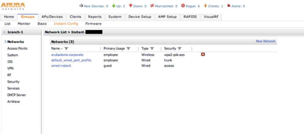
After this step you should be able to manage the IAP the same way you would locally. You should see the clients and statistics as well.
That's it. I hope it helps. :smileywink:
+ Scalability Limits
(ArubaOS 6.3)
Branches — The number of IAP VPN branches that can be terminated on a given controller platform.
Routes — The number of L3 routes supported on the controller.
L3 mode and NAT mode users — The number of trusted users supported on the controller. There is no scale impact on the controller. They are limited only by the number of clients supported per Instant AP.
L2 mode users — The number of L2 mode users are limited to 128000 for 7220 and 7240 and 64000 across all other platforms.
+ Aruba Activate
Thanks boston1630 for the tip.
From the User Guide:
The following example enables the Activate whitelist service on the controller. The add-only parameter allows only the addition of entries to the Activate remote AP whitelist database. This parameter is enabled by default. If this setting is disabled, the activate-whitelist-download command can both add and remove entries from the Activate database.
(host)(config)# activate-service-whitelist
(host)(activate-service-whitelist) #username user2 password pA$$w0rd whitelist-enable (host)(activate-service-whitelist)add-only
The following command is available in enable mode, and prompts the controller to synchronize its remote AP whitelist with the associated whitelist on the Activate server:
(host)# activate whitelist download
For more information check this blog post: What is Aruba Activate?