In the previous posting we discussed, at a high level, the ways in which MIMO can manifest with 11ac solutions.
One case was:
- In the outdoor case for single user MIMO we can introduce a 2nd degree of freedom by using antenna polarization. Polarization is the direction of the electric field. Horizontally and vertically polarized waves are physically and mathematically distinct and so can be used to send 2 streams of independent data. Thus, polarization can be used to create a 2nd degree of freedom in this environment. NOTE: there are only two polarizations that are separate. Anything else is a combination of the two independent states.
First: What is polarization?
When dealing with electric and magnetic field these are vectors which means they have an amplitude and a direction.
In free space the only wave mode that is possible is transverse electromagnetic or TEM wave. This means that the direction of a wave travelling in the Z direction the electric (E) and magnetic (H) fields are described in the plane perpendicular to the direction of propagation. In a Cartesian coordinate system (X,Y,Z) that means that the direction of the E and H field are in the XY plane.
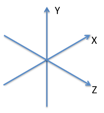
Cartesian Coordinates
So if we imagine an electric field in the x direction the magnetic field will be in the y direction. If we lay a wire in the direction of the x axis the E field will excite the electrons on the wire and current will flow proportional to the strength of the field from the bottom to the top of the wire. That same wire laid across the y or z axis will not see the E field so no current will flow.
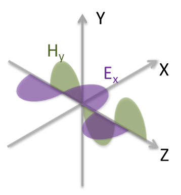
E field in the x direction
Imagine now that we turn the whole system by 90 degrees. Now the E field is in the y direction and the H field is in x direction
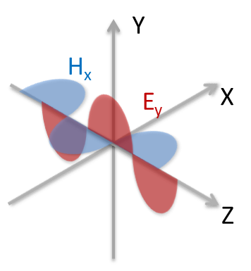
E field in the y direction
As before a wire in the y direction will now be excited by the y directed E field and currents will flow.
For a look at other aspects of polarization check out:
http://en.wikipedia.org/wiki/Polarization_(waves)
In the coordinate system the x and y directions are 90 degrees to one another and they are considered to be physically orthogonal. (i.e. they meet at a right angle).
Since we can physically isolate signals in the x and y directions a communications system can take advantage of this to send independent information on the orthogonal branches. Or putting it in 11ac speak; we can send two streams over dual polarized antenna systems.
Second: A short history of polarization
Since the vector nature of fields was fully described by Maxwell when he set down his equations for electromagnetic fields http://en.wikipedia.org/wiki/Maxwell's_equations, radio systems engineers have exploited this from the earliest days of radio.
Systems with polarization diversity are early examples. In this case the same signal is sent on both streams. This added a level of robustness to a radio link since different polarizations respond differently, for example, to a bounce path that may exist across a lake between the two ends. In the early days the system would detect which path was strongest and simply switch. So this was a switch/polarization diverse system.
Later examples of where this was exploited to add capacity were things like long haul microwave systems for cross country telephony. These required precision antenna design and precision alignment of the feeds to ensure that they were truly orthogonal and the two ends also had to have precision alignment of their vertical and horizontal planes. Even a 1 degree rotational error or leakage from one polarization into the other could result in degradation since the far end had no way of removing the corrupting energy from the desired signal.
With the advent of MIMO processing the days of high precision and high cost installations for 2 stream systems are in the rear view mirror. MIMO operation allows the use of simpler antennas with imperfect polarization isolation and the precision antenna alignment at installation is no longer required.
Third: Practical considerations
In the previous blog the argument was made that polarization diversity has limited benefits indoor since in most practical environment the bounces that occur between the AP and client randomize the polarization of the signals and the simple antenna structures used in client and APs also tend to provide a mix of polarizations. Measurements with discrete antennas show that aside from particular corner cases the use of polarization diverse antenna subsystems indoors provides limited or no benefit and can degrade in other corner cases.
Outdoor is different. In many outdoor cases there very few or no significant reflections paths to distribute the polarization and that same lack of reflections tends to reduce the ability of a system to support multiple streams. The use of polarized antennas outdoors has a significant impact on system throughput.
There is a tradeoff with polarization diversity. Antennas that are cross polarized cannot be combined with beamforming techniques as E fields that are orthogonal cannot be added together. The system designer needs to tradeoff the benefit of the link robustness due to the polarization and the extra signal strength available from beamforming. For access it can be a coin toss. For backhaul it is link distance versus throughput.
For most backhaul solutions and certainly for unlicensed band where the EIRP is regulated the decision is almost always to use polarization diversity and take the benefit of the extra throughput from the additional stream.
Fourth: Cross Polarization and MIMO
Case 1: Aligned Antennas
As mentioned earlier, MIMO makes the use of cross polarization fairly simple. In this section we will look at how MIMO processing can address this.
First let’s look at the source end. Here we have a dual polarized antenna sending signals in the horizontal and vertical directions.
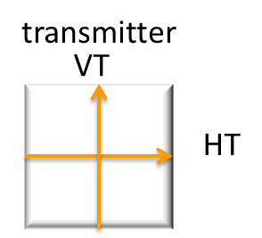
Source antenna with Horizontal and Vertical Polarized Signals
The simplest and ideal case is that the receive antenna is perfectly aligned

Perfectly aligned receive antenna
In a sense the system is akin to looking at yourself in the mirror. The up and down direction is preserved but the sense of left and right is flipped
On the receive antenna the fields looks like
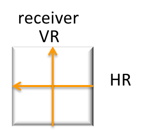
Fields at the receiver
The way that this is represented mathematically is:

Mathematical description of transmitted and received signals
Break this down and you get that VR = 1*VT + 0 *HT and HR = 0 *VT +(-1)*HT
The 2x2 matrix is a description of the propagation channel that exists between the sending and receiving antennas. The receiver in a Wi-Fi radio estimates the channels from the information encoded in pilot tones in the Wi-Fi signal. From that estimate it calculates the inverse of the channel and using that it can calculate what was originally sent.
Let’s take our equation and put it in the standard MIMO form
y=Hx
y is the signal at the receiver,
x is the signal at the transmitter,
H is the channel
Using some simple algebra we can multiply both sides of the equation by the inverse of the channel matrix
H-1y = H-1H x
A matrix multiplied by its inverse give the matrix equivalent of a 1 so this becomes
H-1y = x
In other words if you can measure the channel and derive the inverse you can get back to the original information that was sent.
So let’s take our simple channel estimate

The inverse is in this case is exactly the same (you can check for yourself H-1H).

So to get the original data that was sent
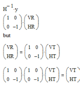
Case 2: Receive Antenna Rotated
Let’s make this a bit more difficult. If the receive antenna is rotated,for example, by 45 degrees relative to the transmitter a traditional non-MIMO system would see this as complete corruption of the original signals as the two polarization would appear to have the same amplitude and give a net signal to interference level of 0 dB.
Again let’s look at the source end. Here we have a dual polarized antenna sending signals in the horizontal and vertical directions.
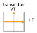
Source antenna with Horizontal and Vertical Polarized Signals
Here is a diagram with the receive antenna rotated to by some angle

Rotated Receive antenna
On the receive antenna the transmitted fields looks like

Fields at the receiver
On the receiver the original vertical and horizontal signals show up evenly on both ports.
To understand what is happening we need to decompose the transmitted signals onto the local coordinates. Will use PR and MR which correspond to the rotated axes on the receive antenna.
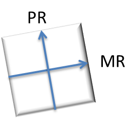
Local Receive Coordinates
If we overlay the transmitted signals onto this:
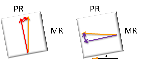
The way that this is represented mathematically is:

Mathematical description of transmitted and received signals
From this it can be seen that as the rotation angle approaches 0 the equation reverts back to what we looked at previously
So now with MIMO processing we can extract the original signals of VT and HT.
Let’s take our equation and put it in the standard MIMO form
y=Hx
y is the signal at the receiver,
x is the signal at the transmitter,
H is the channel
Recall we can multiply both sides of the equation by the inverse of the channel matrix
H-1y = H-1H x
A matrix multiplied by its inverse give the matrix equivalent of a 1 so this becomes
H-1y = x
In other words if you can measure the channel and derive the inverse you can get back to the original information that was sent.
So let’s take our simple channel estimate:

The inverse is in this case is:

So to get the original data that was sent
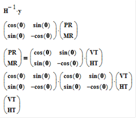
If you want to do the calculation yourself remember that

Summary
So from this we see how MIMO can be used with polarized systems. It makes them easier to deploy and the system works to maximize the operation of the link.
While the above example seems simple, it demonstrates how MIMO processing can be used to solve a practical deployment issue. In future articles we’ll look at how this applies to indoor environments where reflections create the degrees of freedom for MIMO and not necessarily polarization.
Previous Article
http://community.arubanetworks.com/t5/Technology-Blog/Wave-2-Antennas-in-the-spotlight/ba-p/228089
Next Article
http://community.arubanetworks.com/t5/Technology-Blog/Wave-2-MU-MIMO-and-Directional-Antennas/ba-p/238046
@ej_wireless