Controllerless Networks

last person joined: 2 days ago 

Instant Mode - the controllerless Wi-Fi solution that's easy to set up, is loaded with security and smarts, and won't break your budget
Expand all | Collapse all

[Tutorial] RAPNG (IAP-VPN) deployment with AirWave central monitoring and management #mhc

This thread has been viewed 8 times
  • 1.  [Tutorial] RAPNG (IAP-VPN) deployment with AirWave central monitoring and management #mhc

    Posted Mar 13, 2014 04:47 PM

    This tutorial will help you to set up a RAPNG (IAP-VPN) deployment with AirWave central monitoring and management.


    Prerequisites: Basic understanding of Controller, IAP and Airwave configuration.


    RAPNG is the new architecture to provide corporate connectivity to the branch networks. Mostly it differs from normal RAP architecture that it uses IAPs on the remote side.


    Benefits of using RAPNG:

    • IAPs create a local cluster that provides ARM, wIDS/wIPS and other features - it means better and faster RF management.
    • It provides the survivability feature of Instant APs with the VPN connectivity of RAPs 

    • Since the RF management is local, the overhead is much smaller on the tunnel (1-2 Kbps for RAPNG vs. 50-60 Kbps for RAP)
    • Only 1 PEFNG license is needed on the controller (just to enable some of the features). No need for AP/PEFNG/RFProtect licenses.
    • Since the IAPs aren’t actually terminated on the controller the scalability is much better

    Cons:

    • Since 6.3 OS, 620 and 650 controllers doesn’t support IAP-VPN.
    • Clients aren’t visible on the controller. Airwave is recommended for central monitoring.
    • The controller can’t manage IAPs. Airwave is recommended for central management.

    Controller: 3600 - OS 6.3.1.3

    IAP: IAP-135 - 4.0.0.4

    AirWave: 7.7.9


    Required steps:

    Part 1: Configuring the Controller

    Part 2: Configuring IAP

    Part 3: Configuring Airwave for monitoring and central management (optional)


    Part 1: Configuring the Controller


    Step 1:


    First you need to add to the whitelist the mac address of the IAP. You may do this either via GUI or CLI. CLI command:

    whitelist-db rap add mac-address 24:de:c6:xx:xx:xx ap-group rapng

    (Note: The ap-group is not relevant, you can use any group name as it’s not used.)


    Check if it’s in the db:

    show whitelist-db rap 
     
    AP-entry Details
    ----------------
    Name               AP-Group  AP-Name            Full-Name  Authen-Username  Revoke-Text  AP_Authenticated  Description  Date-Added                Enabled  Remote-IP
    ----               --------  -------            ---------  ---------------  -----------  ----------------  -----------  ----------                -------  ---------
    24:de:c6:xx:xx:xx  rapng     24:de:c6:xx:xx:xx                                           Provisioned                    Tue Mar  4 11:46:28 2014  Yes      0.0.0.0
     
    AP Entries: 1


    Step 2:


    The next step is to define a DHCP pool for the IAPs:

    From CLI (you can use GUI as well):

    ip local pool rapng 192.168.20.1 192.168.20.10


    For a basic setup, this is all we need on the controller side.


    Part 2: Configuring IAP


    Step 1:


    Login to IAP GUI.

    From the top right menu choose More and VPN:

    vpn.png


    From the drop-down list select Aruba IPSec. Specify the primary host (along with the backup address if you have one). This is the IP address of the controller interface that will terminate the VPN connection.

    (Note: You can use other protocols such as GRE, you need to check the Aruba Instant User Guide for details)
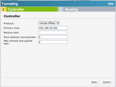
    vpn2.png


    Click Next and you will see the Routing configuration page. You may specify which subnet should be routed to the tunnel. In this example all traffic is routed to the controller.
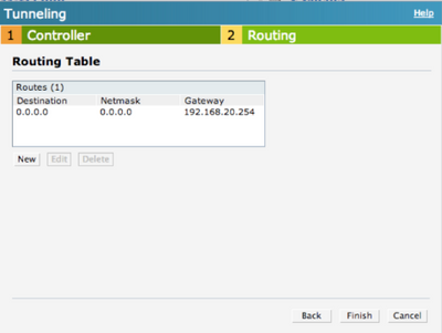
    vpn3.png


    By default, IAP intercepts the DNS traffic and tries to source NAT it locally despite the routing table. If you need to tunnel the DNS traffic you need to specify the enterprise domains in the System settings:

    domain1.png


    If you want to tunnel all DNS traffic you should use *.* wildcard.

    domain2.png


    If the UDP4500 traffic is allowed from the IAP to the host address you specified above, then you should see that the VPN connection is up.

    You may also verify it on the controller by using the show iap table command or checking the Monitoring – Clients part of the GUI.


    show iap table
     
    IAP Branch Table
    ----------------
    Name              VC MAC Address     Status  Inner IP      Assigned Subnet  Assigned Vlan
    ----              --------------     ------  --------      ---------------  -------------
    Instant-XX:XX:XX  24:de:c6:xx:xx:xx  UP      192.168.20.1                   


    Step 2:


    The next step is to define the VLANs that you want to use. In this example VLAN 100 is used. From the More menu choose DHCP Server.

    dhcp1.png


    There are several options for DHCP configuration on the IAP. In this example Centralized L2 DHCP configuration is used. This means that the VLAN physically exists only on the controller and the DHCP server is in the HQ (the IAP acts as a DHCP relay and forwards the DHCP requests to the controller over the VPN tunnel). For details of other options you may check the Aruba Instant User Guide.

    Click on New.

    dhcp2.png


    Enter the name for the VLAN and the VLAN ID. For basic setup the default DHCP relay and Option 82 parameters are fine.

    dhcp3.png


    After clicking OK you should see VLAN name and it’s ID.

    dhcp4.png


    Step 3:


    From this step you may use this VLAN for configuring network access (wired profiles, SSIDs, Dynamic VLAN assignment etc).


    In this example a wireless network has been configured.

    The SSID name is arubademo-corporate.

    ssid1.png


    In the next step VLAN 100 is defined.

    ssid2.png


    ssid3.png


    ssid4.png


    After this step you should be able to see the network and connect clients to it.


    Part 3: Configuring Airwave for monitoring and central management (optional)


    Step 1:


    Go to System settings on the IAP GUI and look for the AirWave section on Admin tab.

    You need to enter the following parameters:

    • Organization: Based on this parameter AirWave will create a new Group for the IAP.
    • Airwave server: The IP address of your AirWave server (you may specify the backup as well if you have one)
    • Shared key: This can be anything, you will NOT need to enter this on the AirWave. This key is used for configuring the first AP in the Instant network.

    (Note: You may use DHCP options to automatically configure the AirWave settings. Please check the Aruba Instant User Guide for details.)

    iapamp2.png


    This is the only thing you need to configure on the IAP.

    (Note: In this example all traffic is tunneled back to the HQ, the IAP communicates with AirWave from its VPN address - via HTTPS)


    Step 2:


    Assuming the communication is OK you should see your IAP as a new device on AirWave. Click on Add.

    amp1.png


    As you can see the group is automatically created. In this example “branch-1” was used.

    amp2.png


    By default, AirWave provides template based management for the IAPs. If you want to use GUI config you need to click on the wrench icon next to the IAP’s group and select “Enable Instant GUI Config”.

    amp3.png


    After this step you should be able to manage the IAP the same way you would locally. You should see the clients and statistics as well.
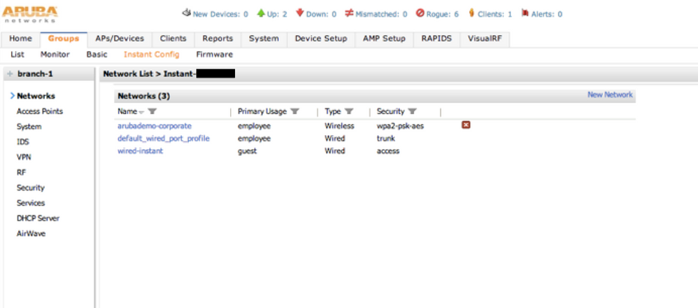
    amp4.png


    That's it. I hope it helps. :smileywink:


    + Scalability Limits

    (ArubaOS 6.3)


     scalability.png


    Branches — The number of IAP VPN branches that can be terminated on a given controller platform.

    Routes — The number of L3 routes supported on the controller.

    L3 mode and NAT mode users — The number of trusted users supported on the controller. There is no scale impact on the controller. They are limited only by the number of clients supported per Instant AP.

    L2 mode users — The number of L2 mode users are limited to 128000 for 7220 and 7240 and 64000 across all other platforms. 


    + Aruba Activate


    Thanks boston1630 for the tip.


    From the User Guide:

    The following example enables the Activate whitelist service on the controller. The add-only parameter allows only the addition of entries to the Activate remote AP whitelist database. This parameter is enabled by default. If this setting is disabled, the activate-whitelist-download command can both add and remove entries from the Activate database.
    (host)(config)# activate-service-whitelist
(host)(activate-service-whitelist) #username user2 password pA$$w0rd whitelist-enable (host)(activate-service-whitelist)add-only
    The following command is available in enable mode, and prompts the controller to synchronize its remote AP whitelist with the associated whitelist on the Activate server:
    (host)# activate whitelist download

     For more information check this blog post: What is Aruba Activate?


    #7220
    #7240
    #3600


  • 2.  RE: [Tutorial] RAPNG (IAP-VPN) deployment with AirWave central monitoring and management #mhc

    Posted Mar 15, 2014 01:36 AM

    This is one of the best posts on this subject that I've seen on the Airheads forum - thanks for sharing! This would have saved me a lot of time a few months back!


    Btw, one thing that may speed up the deployment is adding the following line to the config:


    activate-service-whitelist
       whitelist-enable
       username "youractivateusername@yourdomain.com"
       password <activate password hash>
    !


    Again, thanks for posting!


    -Mike


  • 3.  RE: [Tutorial] RAPNG (IAP-VPN) deployment with AirWave central monitoring and management #mhc

    Posted Mar 15, 2014 10:05 AM

    Thanks for the tip, if you don't mind I attached it to the tutorial.


  • 4.  RE: [Tutorial] RAPNG (IAP-VPN) deployment with AirWave central monitoring and management #mhc

    Posted Mar 15, 2014 12:28 PM

    It's all good - glad it helped!


    -Mike


  • 5.  RE: [Tutorial] RAPNG (IAP-VPN) deployment with AirWave central monitoring and management #mhc

    Posted Mar 17, 2014 12:19 PM

    Added the Scalability Limits information.


  • 6.  RE: [Tutorial] RAPNG (IAP-VPN) deployment with AirWave central monitoring and management #mhc

    Posted Mar 17, 2014 02:28 PM

    Really nice work Zsolti! Many thanks for it.


     It will help a lot to my colleagues to learn the RAPNG style. It's my sad to give you only one Kudo ;)


  • 7.  RE: [Tutorial] RAPNG (IAP-VPN) deployment with AirWave central monitoring and management #mhc

    Posted Mar 26, 2014 06:06 AM

    Thank you Gabor :smileyhappy:


  • 8.  RE: [Tutorial] RAPNG (IAP-VPN) deployment with AirWave central monitoring and management #mhc

    Posted Apr 19, 2014 11:44 PM

    zshusveti


    Great guide! 


    I was having some issues with testing this on an IAP-135, I had some better results on an RAP-3 with using Distributed L2 / L3, although still had issues with Centralized on the Rap-3. 


    With testing the IAP-135 I had issues with all modes. I reviewed your guide and it was a nice tutorial and confirmation that the settings were applied correctly. 


    I did do an upgrade to the latest code, and I was able to test centralized L3 / Distributed L2 on the IAP-135 and it worked right away, I have not tested Distributed L3 and I have not tested the modes on the Rap-3, but I felt there was some sort of bug or mismatch on the code I was using before. I checked the release notes for the IAP and it didn’t say anything specific. I guess it could be the code on the controller as well. I wanted to add this post in case anyone else was having issues. 


    Problematic Code:

    IAP - 6.3.1.2-4.0.0.4_42384

    3200 - 6.3.1.2


    Resolved Code: 

    IAP - 6.3.1.4-4.0.0.5_43022

    3200 - 6.3.1.6


    I have also posted a couple other commands that seemed to come in handy for trouble shooting purposes on the controller. 


    Controller Debug Commands:


    Log Files

    - show log all | include authmgr     -> this will show authentication of the mac address in the whitelist

    - show log all | include ike              -> this will show phase1 / phase2 info


    To view Layer 2 table for client on the Controller and see associated vlan / tunnel ID 


    (Aruba3200) #show datapath  bridge | include 10:93:E9:XX:XX:XX

    10:93:E9:XX:XX:XX  153   153            0          tunnel 11             0


    To view tunnel stats and also find out the inside tunnel address of the IAP, so it can be matched with the command “show iap table” 


    Aruba3200 Controller IP - 172.100.1.100


    (Aruba3200) # show datapath tunnel tunnel-id 11


    Tunnel's: Session Index, Session route/cache Version Number[TSIDX SRTRCV]


     #          Source       Destination    Prt  Type  MTU   VLAN OVLAN       Acls                BSSID          Decaps     Encaps   Heartbeats Cpu QSz TSIDX    SRTRCV   Flags

    ------  --------------  --------------  ---  ----  ----  ---- ----- -------------------  ----------------- ---------- ---------- ---------- --- --- -------- -------- -----

    11      172.100.1.100     172.51.51.1     47   1     1200  0    0     0    0    1    0     00:00:00:00:00:00       1363      13002          0   7   0 56e6     0        TEFPR


      Source IP     Destination IP  Prot SPort DPort  Cntr Prio ToS Age Destination TAge Packets   Bytes     SIDX     SRTI SRCI     SRTRCV UsrIdx   UsrVer   AclVer   Flags

    --------------  --------------  ---- ----- -----  ---- ---- --- --- ----------- ---- -------   -----     -------- ---- -------- ------ -------- -------- -------- -----

    172.100.1.100     172.51.51.1     47   0     0      0/0     7 4   0   local       29a  1759      201526    56e6     0    0        0        3        3        566      FC


    You can also view the  ISAKMP / IPSec SA by the following commands

    - show crypto isakmp sa

    - show crypto ipsec sa 


    Now we can associate the inside IP of the IPSec tunnel with the IAP name. This will also show us what vlans are being bridged over to the IAP 


    (Aruba3200) # show iap table | include 172.51.51.1

    Test-VC  6c:f3:7f:xx:xx:xx  UP      172.51.51.1                   153


    If your using a Distributed L3, you will see the route populated in the aruba controller and you can export this into ospf for ease of use. 


    (Aruba3200) #show ip route


    Codes: C - connected, O - OSPF, R - RIP, S - static

           M - mgmt, U - route usable, * - candidate default, V - RAPNG VPN


    S*    0.0.0.0/0  [1/0] via 172.100.1.1*

    V    192.168.170.8/29 [10/0] ipsec map

    C    172.100.1.0/24 is directly connected

    C    172.51.51.1/32 is an ipsec map x.x.x.x-172.51.51.1


    IAP Debug Commands:


    To view active routes on the IAP 


    Test-VC# show datapath route

    Route Table Entries


           IP             Mask           Gateway       Cost  VLAN  Flags

    ---------------  ---------------  ---------------  ----  ----  -----

    0.0.0.0          0.0.0.0          192.168.1.1          0     0

    172.31.98.0      255.255.254.0    172.31.98.1         0  3333  D

    192.168.153.0    255.255.255.0    172.100.1.100         0     0  T

    192.168.1.0      255.255.255.0  192.168.1.10          0     1  L

    x.x.x.x    255.255.255.255  192.168.1.1          0     0


    IAP VPN Info 

    - show vpn status

    - show vpn config


  • 9.  RE: [Tutorial] RAPNG (IAP-VPN) deployment with AirWave central monitoring and management #mhc

    Posted Dec 03, 2014 07:31 AM

    Been using this guide, but L3 Distributed is a more common and recommended scenario and a few vital points to note there.


    As justink84 said you will need the routing for the inner-ip addresses in your core network. If you don't have OSPF in your network you will not get this to work without adding the necessary static routing.


    Licensing

    Basically you can get this working using everything default without licenses, but some scenarios to thing through here..


    -> If you just want to change just the ACL's for the "default-vpn-role" role you should only need 1 PEFNG license. This is the default role both IAP and RAP gets.


    -> If you want to change the role to anything besides default-vpn-role you need the PEF-V license. You need this if you want different ACL's for RAP and IAP.


    Finally - you want to change the ACL's if you need to the src-nat the traffic coming from the IAP's. This is expecially relevant for the Radius traffic for 802.1x so you don't have to add all IAP VC's as Radius clients.


  • 10.  RE: [Tutorial] RAPNG (IAP-VPN) deployment with AirWave central monitoring and management #mhc

    Posted Feb 04, 2015 03:48 AM

    Hello


    What about the VC IP and Dynamic Radius in this scenario? What do we put there? Inner IP, Outer IP, Local IP?

    Leave it empty and just src-nat the radius traffic from the Controller? 

    That would mean all IAPs in the cluster are radius clients - will that affect performance in any way?


  • 11.  RE: [Tutorial] RAPNG (IAP-VPN) deployment with AirWave central monitoring and management #mhc

    Posted Feb 04, 2015 04:09 AM

    Hi,


    As far as I know VC IP should always be local.

    If you src nat the traffic from the controller then you only need to allow the inner IP as a RADIUS Client. If you happen to use per AP tunnel from the IAP cluster then you have to allow each one of them.

    You may also add a route on the controller to the local subnet using the inner IP as next hop and use VC IP and Dynamic RADIUS Proxy on the IAP side. This way your RADIUS will see the RADIUS packets proxied from the VC IP.


    Zsolt


  • 12.  RE: [Tutorial] RAPNG (IAP-VPN) deployment with AirWave central monitoring and management #mhc

    Posted Feb 04, 2015 10:02 AM


    Since each IAP in the cluster is aware about the VPN routes, I dont see why this would be a problem. The master will still be sending the traffic back to the radius server via tunnel to controller. If you look at the following commands on your IAP's that are not a master. You will be able to see the routes that are injected into the routing table, and they will pass radius requests to the next-hop as the master. From here the Master should route the traffic over the tunnel and your traffic from clearpass will display the VPN Tunnel (Inside) address. 

    - show vpn config

    - show datapath route


    - show iap table


  • 13.  RE: [Tutorial] RAPNG (IAP-VPN) deployment with AirWave central monitoring and management #mhc

    Posted Aug 02, 2015 12:14 PM

    HI all,
    i'm trying to setup this type of infrastructure.
    seems it working fine, but when i try to use a captive portal (exposed by a clearpass server situated into datacenter) authentication seems the HTTP request cannot be handled by the IAP, and the captive portal page isn't showed.

    I think that the issue can be due to the DNS configuration on the IAP.

    i have tunneled all DNS traffic using *.* wildcard, because i need inspect all traffic into datacenter where is an IPS.

    anyway i need the captive portal authentication, any idea to solve this issue?

    Best regards
    Andrea


  • 14.  RE: [Tutorial] RAPNG (IAP-VPN) deployment with AirWave central monitoring and management #mhc

    Posted Aug 02, 2015 05:05 PM

    Andrea, 


    The issue is not DNS needing to be tunneled back to HQ. As captive portal only needs to do DNS interception in order to provide a proper redirect. As long as your allowing some sort of DNS resolution to either the internet or HQ with proper NAT and FW policies, you wont have any issues resolving DNS. 


    To proper determine the issue you may be having with why you cant fwd traffic to clearpass, I would perform the following items when you have the captive portal role selected as default profile. 


    1) validate dns lookups work (nslookup google.com)
    2) validate route exists and is tunneleed for clearpass via IAP, you should see the subnet that states tunneled to HQ, the CPPM IP must also be listed in this subnet / subnets.  (show datapath route)

    3) validate connectivity to clearpass via 443 (telnet x.x.x.x 443)


    If you are not permitted to access CPPM via the web portal then you wont be able to fwd traffic to cppm correctly for the web portal / self provisioning portal.


    Another thing to also keep in mind is where dhcp is being performed and what type of connectivity you have to your network from the IAP. In the case I had configured I have provided an example below for you. 


    IAP DHCP Mode: Local

    IAP DHCP Subnet: 10.51.152.0/24

    IAP IPSec Route: 10.51.0.0/16 next-hop controller-IP


    Controller L2TP Pool: 172.51.51.0/24


    The clearpass server *must* have a route on the network to get back to "172.51.51.0/24" that resides on the controller. If you also look at the static routes via the contorller, you should see the L2TP IP address assigned to that IAP when using VPN Mode. 


    C    172.51.51.2/32 is an ipsec map 74.x.x.x-172.51.51.2


    A default role via IAP has the following policies:

    - Captive Portal "Enforce"

    - Allow access via 443 to CPPM

    - Allow access via icmp to CPPM

    - Allow access to all destinations


    When you look at the datapath session via the IAP, you should not see traffic that is denied going to CPPM. I have provided an example and you can see that a source-nat is being applied when looking at the flags via IAP. If you see a "D" flag when looking at datapath session this means that traffic is denied, and you need to permit it via FW policy on IAP. 


    Client IP: 10.51.151.126

    CPPM: 10.51.20.80

    IAP L2TP: 172.51.51.2


    Flags:

    F - fast age,

    S - src NAT

    N - dest NAT
    D - deny

    Y - no syn
    C - client


    00:0b:86:xx:xx:xx# show datapath session | include 10.51.20.80
    10.51.151.126 10.51.20.80 6 50337 443 0 0 0 1 dev16 d7 FSC

    10.51.20.80 172.51.51.2 6 443 50337 0 0 0 1 dev16 d7 FN


    We can also go one step further and review the session table on the controller and we will see a proper traffic flow existing as well. In my example a source-nat took place on the IAP, we will not see the clients IP actually residing on our network. Your example could be different incase your using different L2/L3 profiles for DHCP. 


    (Aruba3200) #show datapath session | include 10.51.20.80

    172.51.51.2 10.51.20.80 6 50337 443 0/0 0 0 1 tunnel 9 27 0 0 FC
    10.51.20.80 172.51.51.2 6 443 50337 0/0 0 0 1 tunnel 9 27 0 0 F

    Since we have validated the traffic flows exist your web redirect will have taken place as expected. If you are still having issues, it could also be due to the way the External Captive Portal Config is set on the IAP. I had provided an example below that worked.


    External CP Profile:

    Type: Radius

    IP: 10.51.20.80

    URL: /guest/iap-vpn-web-portal.php

    Port: 443

    HTTPs: Enabled

    Capive Portal Failure: n/a

    Auto URL Whitelist: n/a


    Hopefully this info helps you out with getting your captive portal working via IAP VPN Tunnel to controller.


    Justin 


  • 15.  RE: [Tutorial] RAPNG (IAP-VPN) deployment with AirWave central monitoring and management #mhc

    Posted Aug 05, 2015 05:19 AM

    Hi, 


    thanks, i found that the clearpass doesn't have a route to the Inner IP of the access Point, now works!

    I Have other two questions now.


    1) I have connect a second AP to the same LAN, by the master controller i can see the second ap is associated to the first, but seems the clients connected to second AP doesn't have wifi connection.
    So i would understand how it works.
    - I have to specify something?
    - the configuration will be replicated automatically?


    2) I have configured an airwave management server because i'll have to manage different remote locations where i'll place IAP, if I understand correctly i'll have a master AP for each location, correct?


    Anyway i need to chose wich SSID will be propagated from wich AP, Where i can do it?


    Thanks in advance
    Best regards
    Andrea


  • 16.  RE: [Tutorial] RAPNG (IAP-VPN) deployment with AirWave central monitoring and management #mhc

    Posted Aug 05, 2015 10:53 AM

     Andrea,


    Glad you were able to correct the config to get everything working. Was there a reason why you were trying to use a standalone IAP vs converting the IAP's to RAP's and point to the controller? I would recommened using a RAP as it's much easier for mgmt and provisioning. As far as the IAP clusters go, yes a Master IAP would be at every location. This creating more work to manage this. You can setup centralized provisioning in Airwave, and push out templates.  


    Typically if the same IAP's are on the same L2 vlan they will obtain config automatically and join the IAP cluster as long as your allowing IAP's to be auto-joined. Also they must be same firmware or else they will "appear" to join the IAP cluster but not be in sync correctly. Typically the IAP with the longest uptime will chose to be the master, unless you have a usb modem, or different hardware classes. You can also set a specific IAP to be a preferred master, this way if that IAP exists on the network it will always be the preferred master.


    If your using a local DHCP server, that L2 vlan you chose for the vlan for dhcp scope will need to be tagged on every interface on the data switch you have an IAP connected, otherwise dhcp requests will not be passed to the master IAP who is controlling the DHCP server. 


    In regards to your last questions about specific SSID's on specific IAP's. I wanted to make sure I had the correct understanding of what your trying to accomplish. It sounds like you only want a guest SSID to be advertised in specific confrence rooms vs all AP's in that L2 vlan? If this is the case the newer code on the IAP's supports zones. If you dont use zones, then any SSID you have created via the IAP cluster will broadcast on every IAP that resides on that L2 vlan. 


    Justin


  • 17.  RE: [Tutorial] RAPNG (IAP-VPN) deployment with AirWave central monitoring and management #mhc

    Posted Aug 05, 2015 03:36 PM

    Hi,
    the unique reason to use IAP and not RAP is license price.

    I have connected the IAP to Switch port configured in trunk, so the traffic can be tagged with different VALN ID.


    and yes i want that GUEST SSID can be visible only in conference room, i'll try to understand zone utilization.


    thanks =)

    Andrea


  • 18.  RE: [Tutorial] RAPNG (IAP-VPN) deployment with AirWave central monitoring and management #mhc

    Posted Aug 05, 2015 04:16 PM

     Andrea, 


    Happy I could help, and agreed on licensing. Just pm me if you have any additional questions.


    Justin


  • 19.  RE: [Tutorial] RAPNG (IAP-VPN) deployment with AirWave central monitoring and management #mhc

    Posted Aug 06, 2015 06:50 AM

    after adding the tagg for traffic that have to be tunneled on local switch all works fine! 

    thanks!!