802.11 - TIM and DTIM Information Elements
The Traffic Indication Map (TIM) and Delivery Traffic Indication Map (DTIM) is the focus of this blog post. Lets dive deep and understand what these Information Elements are and how they’re used in Wi-Fi communications. Lets break open a frame capture and see them at work!
For clarification there are Information Fields and Information Elements. The TIM and DTIM are Information Elements.
“Information fields are fixed-length mandatory fields in the body of a management frame”
“Information elements are variable in length and are optional.”
802.11 Standard Overview
10.2.1.4 TIM types
Two different TIM types are distinguished: TIM and DTIM. After a DTIM, the AP shall transmit buffered group addressed BUs, before transmitting any individually addressed frames.
The AP shall transmit a TIM with every Beacon frame. Every dot11DTIMPeriod, a TIM of type DTIM is transmitted within a Beacon frame, rather than an ordinary TIM.
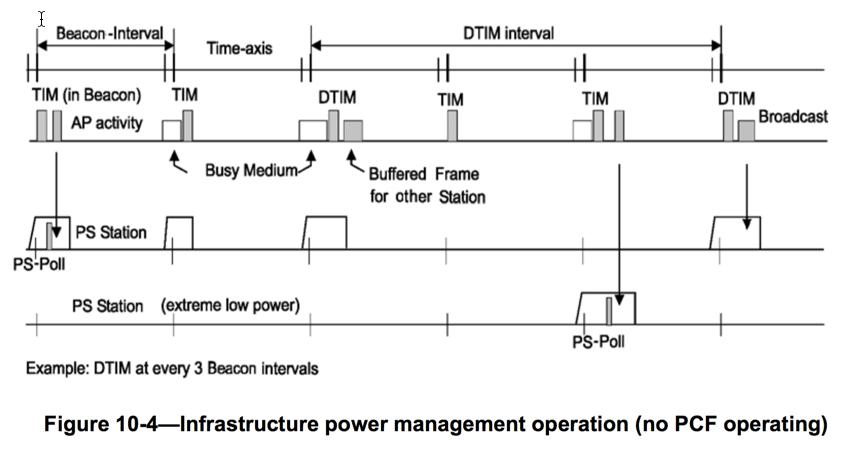
Figure 10-4 illustrates the AP and STA activity under the assumptions that no PCF is operating and that a DTIM is transmitted once every three TIMs. The top line in Figure 10-4 represents the time axis, with the beacon interval shown together with a DTIM Interval of three beacon intervals. The second line depicts AP activity. The AP schedules Beacon frames for transmission every beacon interval, but the Beacon frames may be delayed if there is traffic at the TBTT. This is indicated as “busy medium” on the second line. For the purposes of this figure, the important fact about Beacon frames is that they contain TIMs, some of which are DTIMs. Note that the second STA with ReceiveDTIMs equal to false does not power-on its receiver for all DTIMs.

8.4.2.7 TIM element
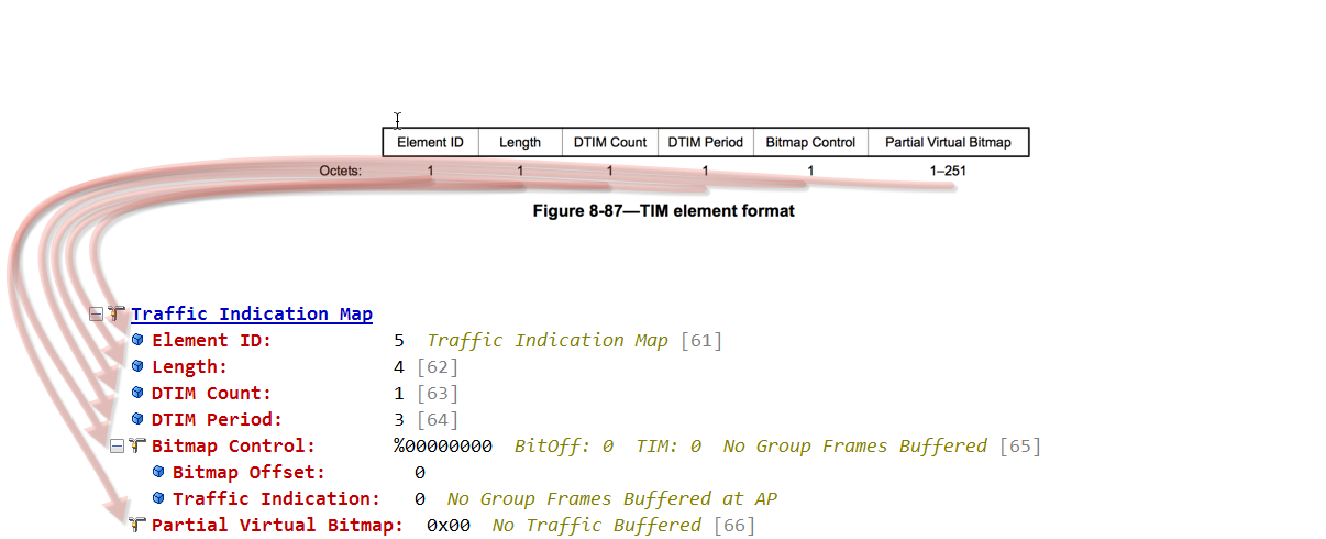
The TIM element contains four fields: DTIM Count, DTIM Period, Bitmap Control, and Partial Virtual Bitmap. See Figure 8-87.

Traffic Indication Map (TIM) -
After reviewing what the 802.11 standard says about TIM. Lets discuss in real world terms what a TIM is and how it works.
You will specifically find TIM in a management frame called a beacon. A beacon is triggered by default on an access point every 102us. Think of a beacon as a network advertisement. The beacon advertises specific <BSSID> wireless network information such as supported PHY rates, security protocols, supported QoS/WMM, vendor specific information and much much more. Included in the beacon is a TIM information element.
Example: BEACON WITH TIM

The TIM information element advertises if any associated stations have buffered UNICAST frames. Stations process the beacon and check the Partial Virtual Bitmap for their AID <Association ID>. A station is given a unique AID during the association process with the access point. This AID is unique to the station and the access point. The AID numbers start from 1 to 2007.
Here is an example of a station being assigned an AID number from the access point in the association response frame.
Example: AID 
The Partial Virtual Bitmap can be found under the TIM IE. The Partial Virtual Bitmap contains AIDs when traffic is buffered at the access point. In this example the AID numbers 1,2,3,4,5,6, and 7 are shown. AID 7 has the bit flipped from 0 to 1. A station processes the beacon and realizes he has UNICAST traffic buffered at the access point. If the Partial Virtual Bitmap does not have AIDs listed its likely there is no buffered frames for any associated clients.
Since this is a partial bitmap there is math at play to calculate which station has traffic buffered. While this blog post doesn't go into the mathematical calculation you can reference the 802.11-2012 standard, page 2626, Part 11: ANNEX O, for these specific calculations.
A station who has buffered frames will proceed with a process called PS-POLL or APSD.
Example: PARTIAL VIRTUAL BITMAP

TIM summary, a station has buffered UNICAST traffic at the access point. This could happen for a number of reasons, off channel scanning or going into a doze state. These are the two most popular reasons. This traffic is buffered at the access point waiting on the station to retrieve it. The station identifies his AID and goes through a process to retrieve his traffic.
Example: ELEMENT FORMAT
The element format matches nicely with our protocol analyzer.

Delivery Traffic Indication Map (DTIM) -
After reviewing what the 802.11 standard says about DTIM. Lets discuss in real world terms what a DTIM is and how it works.
You will specifically find DTIM in a management frame called a beacon under the TIM information element. DTIM is to broadcast / multicast traffic as TIM is to unicast traffic.
Under the TIM you will see DTIM count and DTIM period.
Example: DTIM COUNT / DTIM PERIOD

DTIM Count - This field indicates how many beacon frames till the next DTIM.
A DTIM count field of 0 indicates that TIM is a DTIM.
A DTIM count field of 1 indicates the next beacon is a DTIM.
DTIM Period - This field indicates the beacon intervals till a DTIM.
A DTIM period field of 1 indicates every other beacon is a DTIM.
A DTIM period field of 3 indicates every third beacon is a DTIM.
A DTIM period field of 5 indicates every fifth beacon is a DTIM.
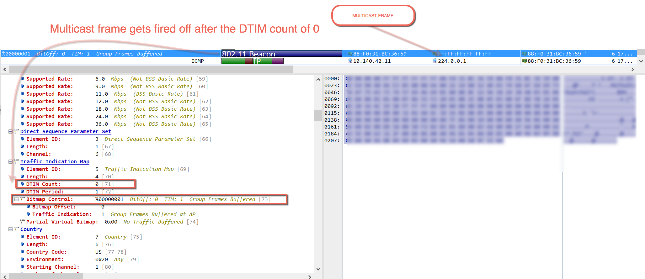
When the first bit of the bitmap control field is set to 1 there is broadcast or multicast traffic buffered at the access point.
Example: BROADCAST / MULTICAST TRAFFIC BUFFERED

DTIM summary, stations are aware of the DTIM transmission intervals when they process beacons. They should awaken or stay awake for the DTIM. DTIM broadcast / multicast traffic is immediately transmitted after the beacon with the DTIM count field of 0.
Example: A DTIM count of zero and a multicast frame being transmitted immediately afterwards.

DTIM CAUTION
Device vendors will make recommendations about specific DTIM requirements. Many will recommend 0 - 3. These values are within reason for some applications. Keep in mind, if a beacon is transmitted at 102us. A DTIM set to 3, equates to a minimum wait period of 306us before a multicast or broadcast frame is transmitted. Sensitive applications relying on multicast or broadcast traffic could be impacted.
Traffic Indication Map Broadcast / Request / Response
As a hobby I enjoy reading the 802.11 standard. You will see the 802.11 standard shares a process call TIM broadcast, request and response. This is a perfect example just because it’s in the 802.11 standard doesn't mean it will be used in the real world. This is not used by any vendors that I’m aware of.
4.3.13.17 TIM broadcast
The TIM broadcast protocol defines a mechanism to enable a STA to receive an indication of buffered individually addressed traffic, independent of the Beacon frame, reducing the wake time of the STA.
8.4.2.85 TIM Broadcast Request element
The TIM Broadcast Request element contains information about the periodic TIM broadcast being requested by the non-AP STA. The format of the TIM Broadcast Request element is shown in Figure 8-339.
8.4.2.86 TIM Broadcast Response element
The TIM Broadcast Response element contains information about the periodic TIM broadcast by the AP. The format of the TIM Broadcast Response element is shown in Figure 8-340.
Thank you for stopping by and I hope this blog was helpful!