Here is a guide to help you set up a Campus WLAN extension. Enjoy!
Matthew L. Bonadies
Campus Network Operations
Wireless Networks
Indiana University - Bloomington
mbonadie@iu.edu
WLAN Extension via AOS-MESH
In this document I will discuss how to create a WLAN network extension with ArubaOS MESH. Typically, placing a new AP requires a data the installation of a data jack. In this example, the customer needed to set up a workstation area that was too far away from the IDF for a CAT6 jack. So, a mesh link will be employed. ArubaOS MESH extension works quite nicely in providing a secure over the air backhaul to extend wireless services to clients. Any access point model in Aruba’s product lineup can be used as a MESH node. This document is to report my example and should not be used as a definitive guide. However, I have included graphics and CLI commands that will aid in the setup of your own WLAN extension.
Definitions:
- Node – MeshPoint or MeshPoint Portal
- MPP – MeshPoint Portal. This is the mesh node that is connected to the wireless controller via Ethernet.
- MP – MeshPoint. This is the node that is both a local access point and MeshPoint connected to the MeshPortal via wireless routing.
- AOS MESH – Wireless routing protocol used between MP and MPP. This protocol is self-healing, and is similar in operation to OSPF (Dykstra). Aruba has made their MESH protocol proprietary and is included in AOS. AOS Mesh is different than MeshConfig and AirMesh.
Figure 1. Pic stolen courtesy of the 6.3 AOS user guide.
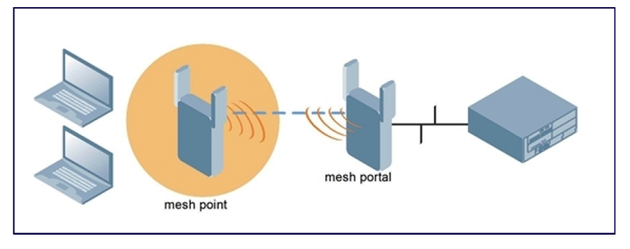
The above picture shows the desired topology. Clients need wireless access in a remote location, and we need to use MESH to provide two-way traffic back to the centralized wireless controllers. Clients will access wireless services on a 2.4 Ghz channel, and the MESH link will be utilized on a 5.8 Ghz channel. In this case, it shall provide minimal overhead/path loss (1 hop) and full connection rates to both the client and between the MESH routers.
In my test, I configured 2 separate AP Profiles. Profile 1 was for the MeshPoint, the other is for the MeshPortal. In each AP Profile you have the ability to control each radio function, and determine which band will be for access/MESH. Here are the basic requirements:
Functionality of system:
- 1 Mesh Cluster with 1 hop
- 1 parent (Portal)
- 1 child (AP)
- Encrypted radio traffic WPA2-PSK-AES between MPP and MP
MeshPoint (MESH+Local Access)
- Separate AP Specific (ap-name) profile
- Secure VAP enabled
- Prefer local access on the 2.4 radio only
- MESH on the 5.8 radio only
- 11a radio is DISABLED in the MeshPoint’s RF profile. MESH config will become default settings for the 11a radio.
MeshPortal (MESH ONLY)
- Separate AP Specific (ap-name) profile
- Secure VAP DISABLED
- No local access
- 2.4 radio DISABLED
- 5.8 radio is MESH only
In order to satisfy the above requirements for each AP separately, you can create an AP Specific Profile for each radio. The two radios need to belong to the same cluster. Make sure to disable/not include a VAP profile and disable the G radio for the MeshPortal. This will disable any local access and create the mesh config as default over the any RF-profile settings. If you do include one, it will provide local access on the same channel as the MESH link thus cutting the bandwidth in half.
Figure 2Visio Graphic – Test Topology Using AP-105’s
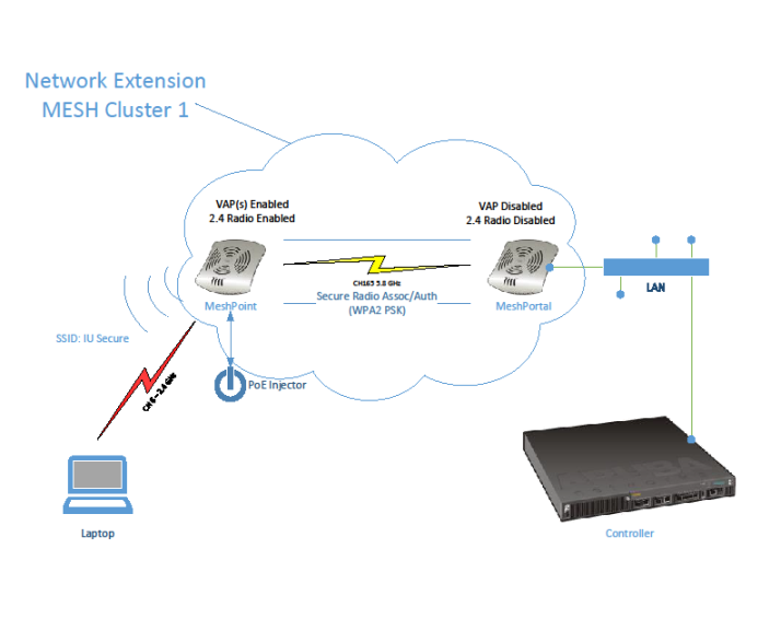
The security is enabled to encrypt user traffic between the MPP and MP. This makes the mesh link more secure. If desired, you can disable security for more bandwidth. Create an AP Group to house the MESH cluster. Once the cluster profile is configured, then creation of the AP Specific profiles may happen.
After configuration of the AP Specific profiles, each radio needs to be provisioned to set its desired functionality. After the MeshPoint is provisioned, it can be unplugged and set up with a PoE Mid-span injector and work as a “stand-alone” access point & MESH link to the MeshPortal. Once all configurations are tested and verified it is time to deploy the system.
Summary:
In summary the campus extension is easy to implement, secure, and provides an excellent alternative to trenching cable or fiber. It can be used in both indoor and outdoor scenarios, but is centrally managed with your master controller. Using ArubaOS and existing Campus AP’s/Infrastructure makes installation a snap. Be sure to understand how AOS Mesh works on separate AP profiles. Also, make sure to have a good quality mid-span PoE inserter and A/C power to power the MeshPoint.
Options and Further Considerations:
- External antennas can be used to enhance MESH link RF propagation.
- AP-130/220 series radios can be used for 3x3 MIMO connection rates and faster processing. This will help with MESH overhead.
- Good idea for outdoor extensions.
- Can help customer save money at times.
- Good option for your “bag of tricks”.
- Mesh config can be used to set up stand-alone AP’s with battery packs for passive RF surveys in new buildings. This one is cool.
Sources:
- Aruba Outdoor MIMO wireless Networks VRD; http://www.arubanetworks.com/vrd/OutdoorMIMOVRD/wwhelp/wwhimpl/js/html/wwhelp.htm
- Aruba Networks AOS 6.3 user guide; http://support.arubanetworks.com/Documentation/tabid/77/DMXModule/512/Command/Core_Download/Default.aspx?EntryId=13878; pg. 447-466
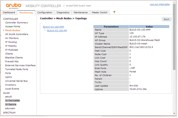
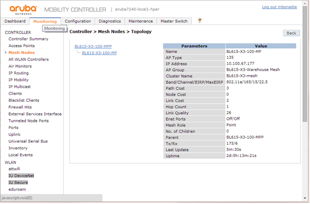
MESH Tree in Local Controller:
Throughput Test – TCP/UDP:
Here is a basic throughput test for the MESH. Both client and server were on the same testing SSID/VLAN.
Figure 3. AP-105 MPP on Desk & MP 100’ away.
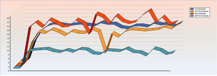
TCP Up: 18.25 Mbps (Ave: 16.89) UDP Up: 24.38 Mbps (Ave: 21.68), Loss: 9.2%
TCP Down: 5.70 Mbps (Ave: 14.55) UDP Down: 7.49 Mbps (Ave: 8.14), Loss: 9.7%
Round-trip time: 8.0 ms
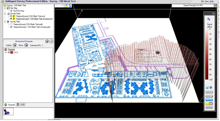
Survey Results – Meshpoint Local Access:
Figure 4. 2D Heatmap of MeshPoint
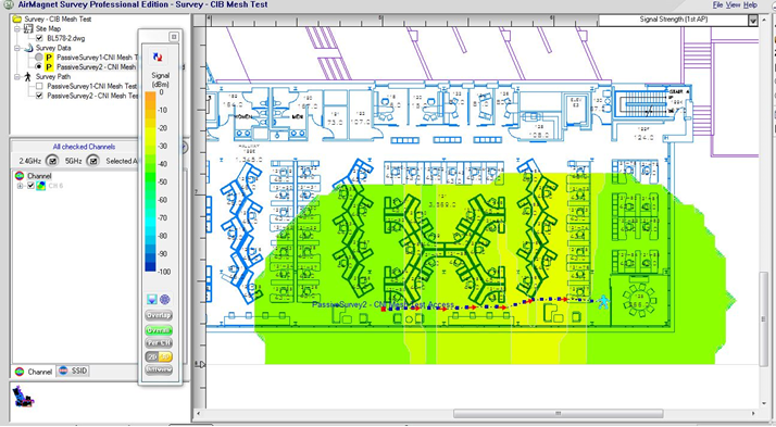
Figure 5. 3D Heatmap of MeshPoint.
MESH Config – 2 Radio profile example:
ap mesh-cluster-profile "BL615-warehouse-mesh"
cluster "warehouse-mesh"
opmode wpa2-psk-aes
wpa-hexkey (your key here)
wpa-passphrase (your passphrase here)
!
rf dot11a-radio-profile "BL615-mesh-a"
no radio-enable
interference-immunity 3
!
rf dot11g-radio-profile "BL615-mesh-g"
interference-immunity 3
!
ap-group "BL615-X3-MeshPoint-Portal"
dot11a-radio-profile "BL615-mesh-a"
dot11g-radio-profile "BL615-mesh-g"
ap-system-profile "aps_group25"
mesh-cluster-profile "BL615-warehouse-mesh" priority 1
!
ap-group "BL615-X3-MeshPoint-Access"
virtual-ap "iu-secure-cni-vap"
dot11a-radio-profile "BL615-mesh-a"
dot11g-radio-profile "BL615-mesh-g"
mesh-cluster-profile "BL615-warehouse-mesh" priority 1
!
ap-name "BL615-X3-100-MP"
virtual-ap "iu_secure-vap"
dot11a-radio-profile "A-RADIO-DISABLE"
!
ap-name "BL615-X3-100-MPP"
dot11g-radio-profile "2.4-DISABLE"
!