Requirement:
We are testing here the default gateway fail-over for the client which will have Virtual Router ID set on themselves as the Default gateway. Aruba 3810M Switch is acting as unmanaged L2 device connected to, two L3 Aruba 6300M Switches where we would have the VRRP configured and we would extend those connection to ISP Router which is one more Aruba 6300M Switch. We would have a loopback which should be reachable from the client using the Master Router.
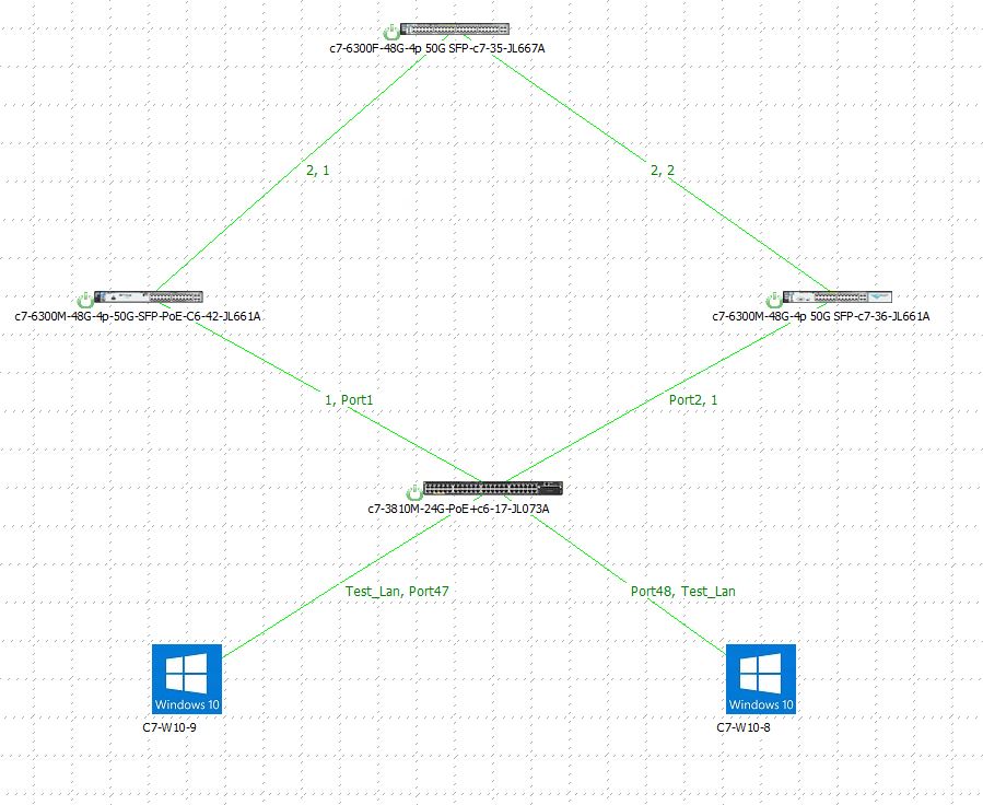
Below is the extended topology for testing default gateway fail-over using Virtual Router Redundancy Protocol with Preemption (VRRP):-
Below is the Devices Information in the topology:-
1. C7-6300M-48G-4p-50G-SFP-PoE-C6-42-JL661A - Host_Name- 631
2. C7-6300M-48G-4p-50G-SFP-PoE-C7-36-JL661A - Host_Name- 632
3. C7-3810M-24G-PoE+C6-17-JL073A - Host_Name- Sw1
4. C7-W10-9 and C7-W10-8 - Two hosts with the Default Gateway set to the Virtual IP.
Solution:Why we need VRRP (Virtual Router Redundancy Protocol) with active preemption method?
Answer:- When we run VRRP on a router with priority, it signifies the best device to act like a L3 / Router for all the routing decisions to be made and should have the best CPU performance. However, the Backup router is just for the temporary use just in case of schedule maintenance on the Master or a real device failure but the enterprise has to be rely on the Master device and expect it to come back up as early as possible.
With Preemption mode, having a higher priority, we can influence the Master, Backup router election in VRRP and make sure the Master should always be the Master after any scheduled or unexpected fail-over.
Preempt : It is a state in which one of the backup routers become the master router (when the master router goes down). Also, when the master router comes up again, it will become the master router as it’s priority is still higher.
- Preempt mode : When a router operates in preempt mode, it will take over the virtual router master role whenever it has a higher vrrp priority than the current Master. The router sees the advertisements with a lower priority and sends a preempt message telling the device with the lower priority to become a backup router. It also begins sending its own advertisements. The preempt mode applies when you add a new router with higher priority to the virtual router. It also applies when a failed master is restored. That router assumes the master role again because it has the higher priority.
- Non-preempt mode : If a router is using non-preempt mode, the router does not attempt to take over the master role from an active master even if it has a higher priority. This behavior holds the true whether the backup router with a higher priority is a new device or a former master that failed.
Master router : One of the VRRP group member is elected as master router which takes up the responsibility of forwarding the local traffic. The router is elected on the basis of VRRP priority. If some group member of VRRP group has higher priority than others then it will be elected as master router. If the priority is same(by default 100) then the router having the highest IP address will become the master router.
Backup routers : Only one of the VRRP group member will become the master router while others will be back up routers. In case the master router fails then one of the backup routers will become master router.
Master advertisement timer : The master router multicast the keep-alive messages at 224.0.0.18 in every 1 second.
Master dead timer : The time in which the backup router will take up the responsibilities of Master router if the master advertisement message is not received. It is, by default, 3.69 seconds.
Configuration:A VRRP router is configured to run the VRRP protocol in conjunction with one or more other routers attached to a LAN. In a VRRP configuration, one router is elected as the virtual router Master, with the other routers acting as backups in case the virtual router master fails.
In our topology, we are using Preempt mode. Hence, vrrp priority is given to the Router 631, also we are connected to the ISP Router, via both the VRRP routers 631 and 632. We are using routed ports to have all the connectivity point to point and exchange those routes using OSPF. We have configured a loopback address on the ISP Router or the Top router which in our case is the internet IP: 172.172.172.172, which should be reachable all the way from the client machines at any point of time in case of fail-over, also when Master comes back up as it original state.
Below is the configuration of the devices:-
Router 631:-
631# show running-config
Current configuration:
--Extra Outputs have been Omitted--
router ospf 1
area 0.0.0.0
interface 1/1/1
no shutdown
routing
ip address 192.168.1.1/24
ip ospf 1 area 0.0.0.0
vrrp 1 address-family ipv4
address 192.168.1.100 primary
priority 101
no shutdown
exit
interface 1/1/2
no shutdown
routing
ip address 21.21.21.22/24
ip ospf 1 area 0.0.0.0
Router 632:-
632# show running-config
Current configuration:
--Extra Outputs have been Omitted--
router ospf 1
area 0.0.0.0
interface 1/1/1
no shutdown
routing
ip address 192.168.1.2/24
ip ospf 1 area 0.0.0.0
vrrp 1 address-family ipv4
address 192.168.1.100 primary
no shutdown
exit
interface 1/1/2
no shutdown
routing
ip address 22.22.22.21/24
ip ospf 1 area 0.0.0.0
ISP Router:-
Router# show running-config
Current configuration:
--Extra Outputs have been Omitted--
router ospf 1
area 0.0.0.0
interface 1/1/1
no shutdown
routing
ip address 21.21.21.21/24
ip ospf 1 area 0.0.0.0
interface 1/1/2
no shutdown
routing
ip address 22.22.22.22/24
ip ospf 1 area 0.0.0.0
interface loopback 1
ip address 172.172.172.172/24
ip ospf 1 area 0.0.0.0
L2 Switch Configuration:
Running configuration:
; JL073A Configuration Editor; Created on release #KB.16.03.0004
; Ver #10:08.7f.ff.bb.ff.7c.59.fc.7b.ff.ff.fc.ff.ff.3f.ef:52
hostname "Sw1"
module 1 type jl073x
flexible-module A type JL083A
snmp-server community "public" unrestricted
oobm
ip address dhcp-bootp
exit
vlan 1
name "DEFAULT_VLAN"
untagged 1-24,A1-A4
no ip address
exit
****************************** You may see in the Switch we have not configured anything, it is just carrying and forwarding the default VLAN's broadcast (VLAN 1).
Here is the Host's / Client's IP Address configuration with Virtual IP address:
Client 1 IP Address Configuration:

Client 2 IP Address Configuration:

Connectivity From Routers to the Switch and hence to the clients:
Router 631(Port # 1/1/1) <<=>> (Port # 1) Aruba 3810M
Router 632(Port # 1/1/1) <<=>> (Port # 2) Aruba 3810M

Aruba 3810M (Port # 23) <<=>> Client 1 - IP Address - 192.168.1.254 255.255.255.0 |Default Gateway - 192.168.1.100
Aruba 3810M (Port # 24) <<=>> Client 1 - IP Address - 192.168.1.155 255.255.255.0 |Default Gateway - 192.168.1.100

Below is the ISP Router connectivity information:-
On Router Port # 1/1/1 <==> Port # 1/1/2 (Router 631)
On Router Port # 1/1/2 <==> Port # 1/1/2 (Router 632)

VerificationIn this part, we would see that when we disable the link to the Master VRRP router the loopback IP (172.172.172.172/24) on the ISP router would not fail to ping as the default gateway will fail to the the Backup router. Hence, as soon as we re-enable the Master VRRP router which has the priority of 101, will retain its previous role as Master. This will show the Preemption behavior of the VRRP protocol.
We would initiate the Continuous ping from the Host: 192.168.1.254/24 to the Loopback of the ISP Router: 172.172.172.172/24.


As the LLDP information on the Layer 2 Switch "Sw1", we would disable the Port # 1, so that VRRP Master should fail to Backup.


So we disabled the Port # 1 in the below screenshot and re-enabled it.

You may see the transition in the role for Master router below:-

The Backup router holds the temporary role and then came back to the Back role again as we have the VRRP priority set on the Router 631 to be the Master:-

How to verify the same using Wireshark Packet Capture is shown below, run the Capture on wireshark with the filter ip.addr==192.168.1.155 && ip.addr==172.172.172.172.
**Note:- All captures should be done while running continuous ping towards Loopback IP Address on the ISP Router: 172.172.172.172/24. In this demonstration, we running continuous pings and Wireshark Captures from the Host # C7-W10-8, with IP Address: 192.168.1.155/24
Wireshark Test 1 || Step: 1 - Run the Capture on wireshark with the filter ip.addr==192.168.1.155 && ip.addr==172.172.172.172.
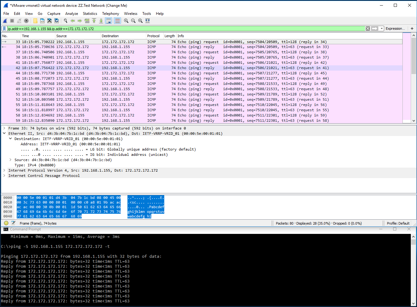
In the above Capture, you may see the Frame: 33 information, which is sourcing from the VMNIC: d43b04-7b1cbd and destined to the VRRP: Virtual MAC Address: 00:00:5E:00:01:01, of the Master Switch.
Below is the reply packet for Frame: 34, which is sourcing from VRRP: Virtual MAC Address: 00:00:5E:00:01:01, to VMNIC: d43b04-7b1cbd.

Hence, it is clear that the reply and response for the client from the network on the ISP Router is taken care by the VRRP Master only with the Virtual IP Address: 192.168.1.100.
In order to test Path, you may add a Switch to see what are hops it is taking. For example, I just extended my topology by adding one Aruba 2540 Switch to Aruba 3810 Switch, assigned an IP address: 192.168.1.141/24 and set the Default Gateway to the 192.168.1.100 - Virtual IP. Hence, it would give the exact path it is taking to hit the Loopback IP : 172.172.172.172/24 on the ISP router.
Please follow the below screenshot of the Extended Topology and the traceroute results:-
Running Configuration of the Test Switch to see the hops or path taken to reach the Loopback of the ISP Router:-

Below are the traceroute results without Fail-over and with Fail-over:-
1. Without Fail-over is the scenario where it takes the path of Master router 192.168.1.1/24:-


2. With Fail-over is the scenario where it takes the path of Backup router 192.168.1.2/24:-

