Part 1
This article is the first of a series on IRF, its architecture, behavior, benefits, and best practices.
IRF basics
What does IRF mean? IRF stands for Intelligent Resilient Framework
Is IRF new? IRF has been around for over 10 years
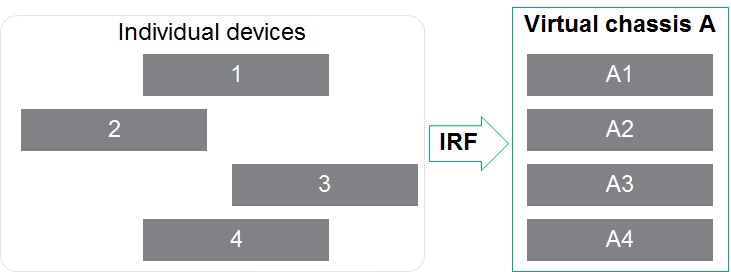
What is it? It is a technology supported on HPE FlexNetwork switches and (some) routers. It aggregates 2 or more networking devices into a single switching and routing entity called an IRF-fabric or IRF-stack.
How does it work? The internal and external behavior mimics a chassis-based device. For example an IRF stack of up to 9 "stackable" switches behaves as a single chassis.
Diagram 1: device aggregation with IRF

What is the most important benefit of IRF on core and distribution switches? IRF provides device-level redundancy while preserving simplicity.
For example, suppose you need to build a 3 tier campus LAN and decide that your access layer will only be Layer 2. In other words, you routing edge is the aggregation/distribution layer. And you are deploying 2 modular switches as the core and at each distribution point. Access switches are connected to both distribution switches in their building to provide redundant paths.
So, from the physical point of view, the access switch is part of a loop - see the diagram below - and to prevent all bad things that happen with Ethernet loops, you are foced to deploy MSTP.
Diagram 2. 3-tier LAN without IRF

MSTP solves the "loop issue" and provides VLAN-based load balancing. However, the complexity has not been completely eliminated: the aggregation switches are a pair of IP gateways for all the clients connected to that access switch. Now, to manage the IP gateway redundancy, you must deploy VRRP.
With IRF, as both aggregation switches are now one, instead of using MSTP to prevent loops and manage L2 link redundancy, you can implement link aggregation: now you have better load balancing and shorter recovery times. And, again, because these two switches are one, there is only one IP gateway (the IP interface is shared by both devices), there is no need for VRRP.
Diagram 3. 3-tier LAN with IRF

And finally, the network now looks (logically) like a tree.
Diagram 2. 3-tier LAN without IRF - logical view
 \
\
In the following article we will discuss the IRF architecture for stackable switches and later for modular switches.