Overview
The aim of this post is to show how to add a switch into an existing Central managed environment.
Everything will be done remotely; no local console access or cable swapping required. It is designed to simulate the process of manually expanding a remote network with no onsite skills required.
Environment
Central 2.4.9 is the base platform. It is expected that the coming upgrade to 2.5.0 will change some of the details, but the process flow remains consistent.
This demonstration environment has 3 existing switches, and the fourth one will be added:
- Core switch = 5406R managed in Central with a template
- 2930F-29 (24 port) managed in Central with GUI and CLI access (hybrid)
- 2930F-28 (8 port) managed in Central with GUI and CLI access (hybrid)
- Switch 4 = 2930F (8 port) <-- this is the new one to be deployed
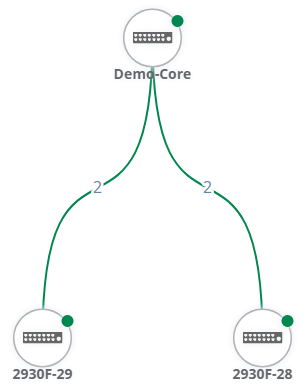
Process Overview
- Prepare the core switch
- Plug and power new switch
- Wait for it to appear in Central
- Create a new group and assign the switch to it
- Initial switch configuration via the Central GUI
- Check link status
- Prepare new switch trunk
- Configure core trunk
- Verify connection status
- Complete GUI Config
- Additional switch config (eg colourless ports and other config not currently possible in the GUI)
1. Prepare the core switch
- Assign the ports (in this case A22 & C22)
- and set the appropriate VLAN
- Shutdown one of the ports (not strictly necessary since spanning tree is running on the core already, but it makes downstream port identification easier)
Note that default startup VLAN is always VLAN 1, and Central does not change that.
Template changes
These are the changes made in the template and automatically pushed out to the 5406R:

interface A22
   name "New switch"
   exit
interface C22
   disable
   name "New switch"
   exit
vlan 1
   name "DEFAULT_VLAN"
   no untagged A1-A20,A22,A24,B1-B24,C1-C20,C22,C24,D1-D8,Trk21-Trk23
vlan 930
   untagged A22,C19-C20,C22,C24,Trk21,Trk23
Ports in Bold above have been added to the command.
2. Plug in new switch
- The new switch needs to be in the brand-new, out-of-the-box factory-default state
- connect the new switch (using a pair of 3m DAC cables in this case)
- New switch uplink ports are the two SFP+ ports 9 & 10
- Power it on
3. Check Central
The new switch should appear in Central as an unassigned device.
If it doesn't, Activate may need to be updated to include it, or it may need to be manually added (Add Devices under Global Settings | Device Inventory)
It may take a few minutes to show up in Central.
Check in Global Settings | Device Inventory
4. New Group
Under Global Settings | Manage Groups, create a new switch GUI group (enter group name and password; don't tick the switch checkbox).
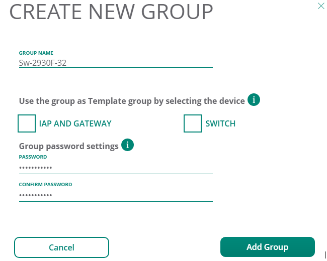
Move the new switch from unassigned into the new group (Sw-2930F-32).
It should be visible under Monitoring & Reports | Network Overview

5. Central GUI Initial Switch Config
From Wired Management, choose the new switch group and make the initial config changes in the GUI.
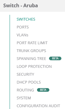
I will initially configure the following:
- SWITCHES: Switch name and contact/loctaion details
- PORTS: I like to label the uplink ports, but it isn't necessary
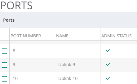
- VLANs: add the new management VLAN (250) and IP address (10.20.50.32/24)
- SYSTEM: set a suitable name server (eg a local one or 8.8.8.8)
Once these changes are made, check that the config is still in sync with CONFIGURATION AUDIT.
6. Check Link Status
There are two connections, but only one is active. It is important to know which one is active so that the trunk configuration can be made to the other. That allows a roll-back process in case something goes wrong.
Using Central GUI
Sticking with the GUI theme, you can add the new switch to the existing group or site used to display the network topology. In this example, I added the new switch to the Site "Coffs Harbour"
The topology view for Coffs Harbour will soon show the new switch as well.
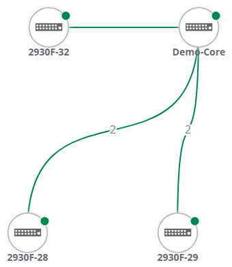
Note the link between the 2930F-32 (new switch) and Demo-Core doesn't have a 2 - just a single link from the pair is active. Spanning tree on the core will be blocking one connection to stop a loop forming.
Hovering over the link shows the active ports (9 - A22)

Using Central CLI
The alternate method is to use the console from Central.
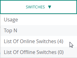
- From Network Overview, choose Switches, List of Online Switches
- Select the new switch
- Click the drop-down "Actions" and select Console
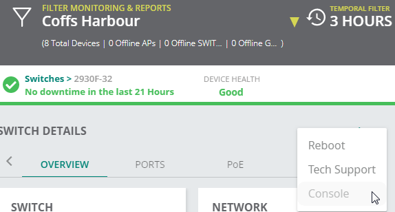
Central will present a console login screen:

You now have console access to the switch!
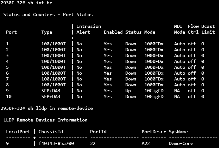
7. Prepare New Switch Trunk
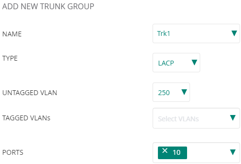
Navigate to Wired Management | TRUNK GROUPS for the new switch, and click the plus to add a new trunk.
Just add port 10 to trk1 LACP. Choose the management VLAN (250) as untagged.
Add a default routing entry that will use the management VLAN link.
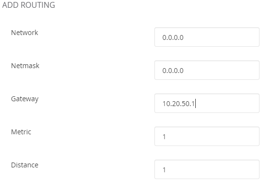
Click the routing toggle to enable.
8. Configure Core Trunk
This core is configured with a Central template rather than the GUI.
The template will be modified to create the LACP trunk.
Make these changes to the existing template:
trunk A22,C22 trk22 lacp

interface C22
   enable
   exit

vlan 1
   no untagged A1-A20,A22,A24,B1-B24,C1-C20,C22,C24,D1-D8,Trk21-Trk23
   exit

vlan 250
   untagged A2-A20,A24,B1-B24,C1-C18,Trk22
   exit

vlan 930
   untagged C1-C4,C19-C20,C22,C24,Trk21,Trk23
   exit
9. Verify Connection Status
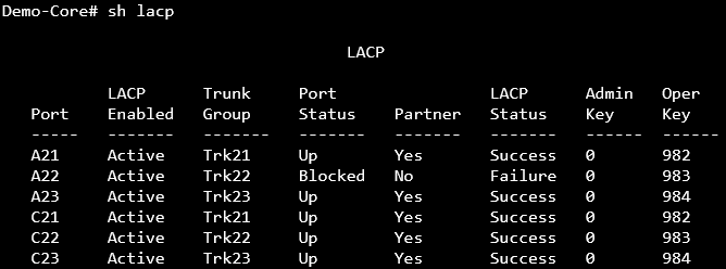
You should now have an aggregation (trunk) group between the core and the new switch. However, since port 9 on the new switch is still in access mode (so that there was a way to regain control if something went wrong), only one of the two links is actually working with LACP. This can be seen using Central CLI to the core:
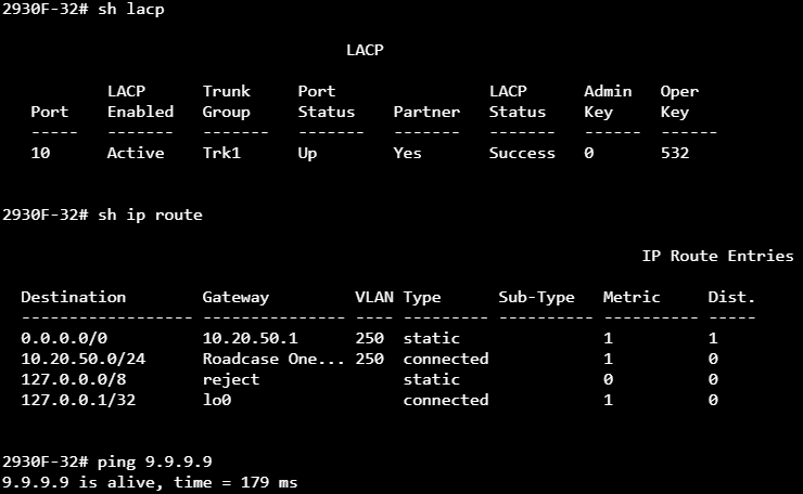
Using Central CLI to the new switch, we can see the one link is active, routing via the management VLAN is fuctional.
10. Complete GUI Config
The second port on the new switch can now be added to the trunk to complete the link configuration.
Edit the existing Trk1, and add the second port (9) to the trunk.

Turning on spanning tree is a good idea now too.
- Enable MSTP
- set priority
- enable root-guard on access ports
After the config is pushed out, the LACP Trunk will show both connections with a partner.

11. Central CLI Additional Switch Config
There will almost certainly be config options that are not currently supported by the GUI that can be entered here to complete the switch config.
Note that as new features are added to the GUI in Central, you should expect that they will overwrite CLI-configured settings.
One of my previous posts has examples of this:
https://community.arubanetworks.com/t5/Cloud-Managed-Networks/Managing-a-wired-and-wireless-site-with-Central/td-p/549194
Console Access
Console access is required for making changes in hybrid mode, and can provide useful additional testing and troubleshooting capabilities.
One of the first things I do for switch hardening is to configure authorised-managers. However, this will stop Central console access with this error message:

This is easily fixed by adding 127.0.0.1 with this syntax:
ip authorized-managers 127.0.0.1 255.0.0.0 access manager